NETELAB
hardware platform for educational research laboratory works
on physics, electrotechinic and electronics related disciplines
Application
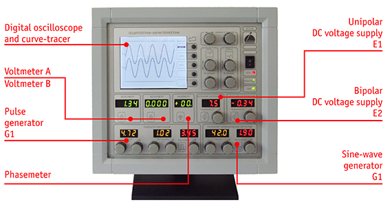
Equipment set NETELAB is designed to provide studying of various physical phenomena, characteristics and behavior of electronic circuits and schemes, and to give basics and grow a skills in practical work with modern measurement equipment. Set includes one or some individual workplaces.
Each workplace consist of instrumental unit (includes 2 PSUs, 2 signal generators, digital voltemeters, phasemeter, digital oscilloscope and curve-tracer) and measurement unit (allows to assembly various electrical and electronic schemes).

Essential features
Operational mode of NETELAB by default is autonomous. Provided a functionality for equipment control and data transfer through LAN, which allows a teacher to monitor student’s activity and work progress.
NETELAB’s features:
- rugged design of operator controls;
- possibility to limit signal parameter’s ranges and certain devices blocking to prevent equipment damage if laboratory work is carried by newbies
- complexing of measurement and generating tools to provide operation of NETELAB as multifunctional curve-tracer allowing to demonstrate experimental characteristics curves
uВХ(f), uВЫХ(uВХ), uВХ(iВХ) to intensify studying process of frequency response, resonance phenomena, nonlinear elements characteristics and various circuit, containing nonlinear elements - results deminstration on common presentation display equipment (optional)
- resulting oscillogram images transfer through wireless network (optional)
Characteristics
DC voltage offset supply |
|||
| Output voltage adjustment range, V |
–5...+5
|
||
| Output impedance , Ohm |
0.1
|
||
| Max output current, A |
0.1
|
||
| Current value limiting control |
yes
|
||
DC voltage power supply |
|||
| Output voltage adjustment range, V |
+1 ... +9
|
||
| Output impedance , Ohm |
0.1
|
||
| Max output current, A |
0.1
|
||
| Current value limiting control |
yes
|
||
Sine-wave signal generator |
|||
| Operating frequency range, kHz | 0.100 … 99.9 | ||
| Signal amplitude, V |
0.05 … 5.0
|
||
| Output impedance , Ohm |
0.1
|
||
| Max output current, A |
0.3
|
||
| Current value limiting control |
yes
|
||
| Pulse generator | |||
| Pulse repetition interval, ms | 0.200 … 999.0 | ||
| Pulse duration, ms | 0.100 … 9.980 | ||
| Pulse amplitude, V |
0.05 … 5.0
|
||
| Output impedance , Ohm |
0.1
|
||
| Max output current, A |
0.3
|
||
| Current value limiting control |
yes
|
||
| Voltmeters A and B | |||
| Measured voltages range, V |
0.1 … 100
|
||
| Input impedance, Mohm |
1
|
||
| Phasemeter | |||
| Operating frequency range, kHz |
0.010 … 100
|
||
| Accuracy, deg., not worse |
1
|
||
| Sign indication |
yes
|
||
| Oscilloscope and curve-tracer | |||
| Channels |
2
|
||
| Screen resolution, pixels |
320 х 240
|
||
| Vertical graduating mark, V |
10, 5, 2.5 … 0.025, 0.01
|
||
| Horizontal graduating mark, s |
0,5; 0,25; 0,1; … 10•10-6
|
||


 Русский